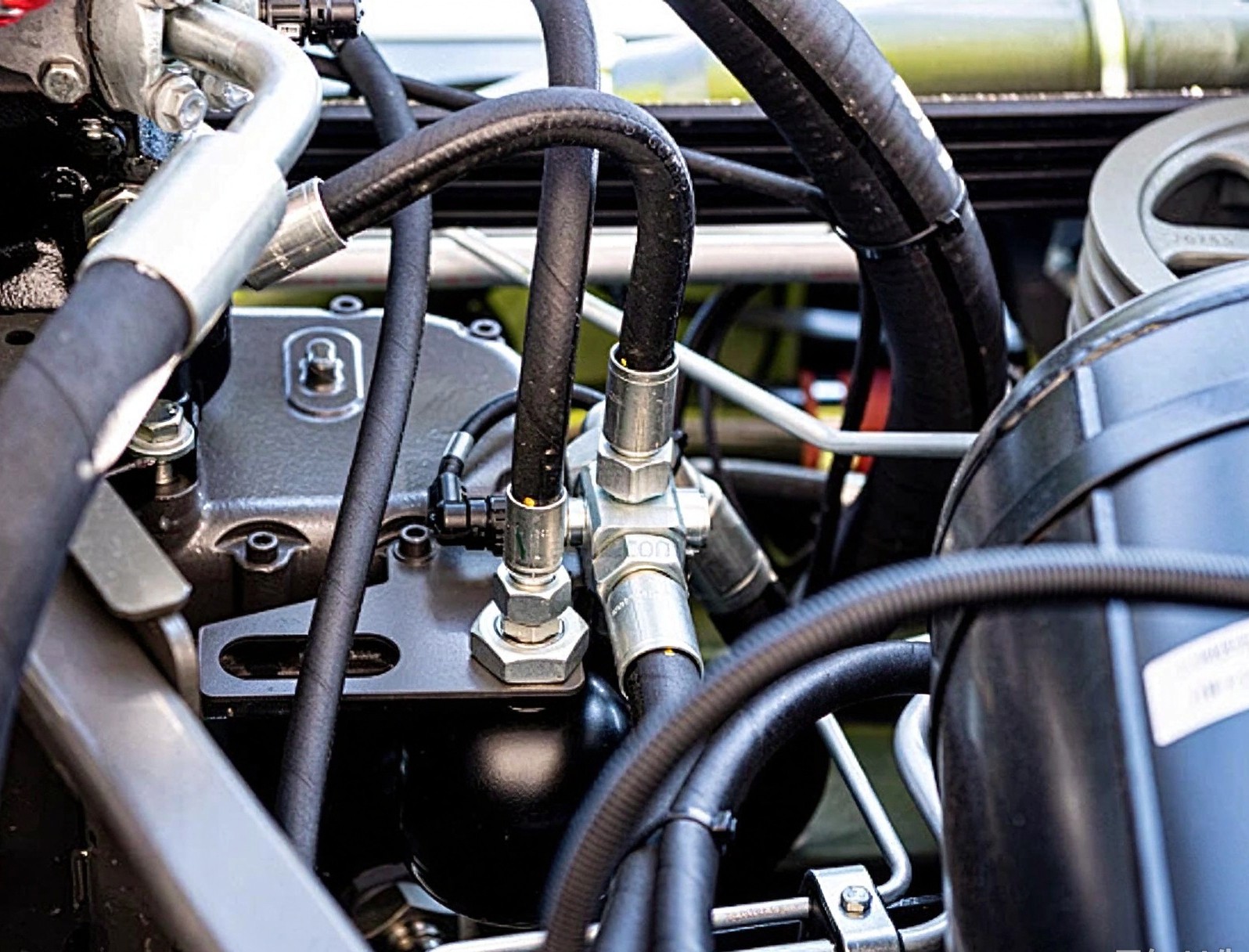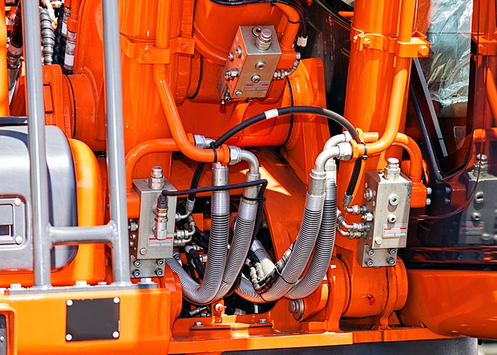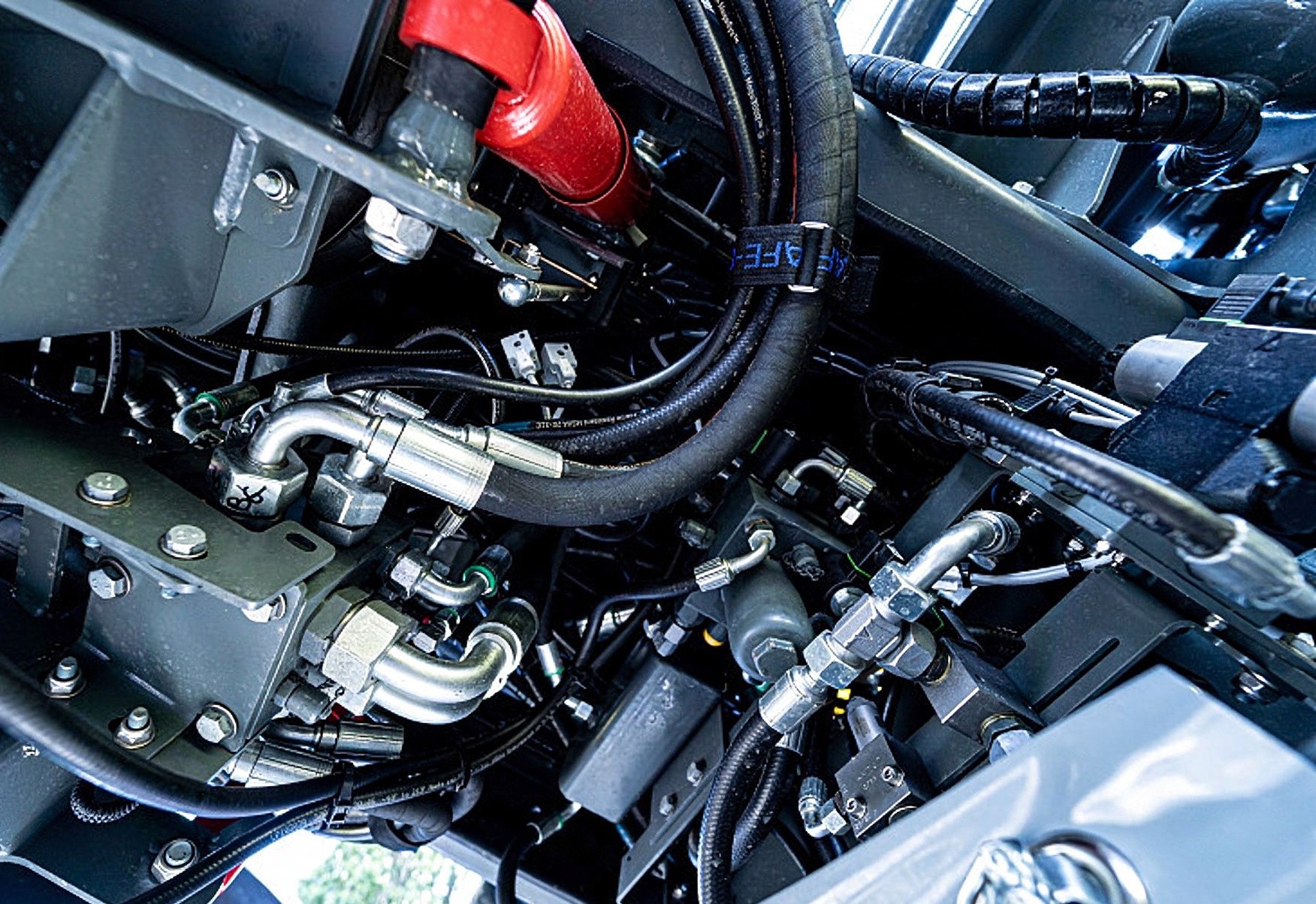
Length, elbow orientation and end fittings differ for every machine and every mounting position. The custom process looks straightforward: take measurements, place the order, produce per your drawing, and inspect on arrival. Yet hidden pitfalls at any step can render the whole assembly useless. A large share of returned hose assemblies are not due to quality defects, but incorrect measuring references marked on drawings. Half the quality of a hose assembly depends on the factory; the other half lies on the drawing you submit with your order.
Length Reference: Clearly define where to measure from and to
There are accepted industry conventions for hose assembly length: from fitting face to opposite fitting face. For elbow assemblies, measure along the hose centerline to the intersection point of the elbow centerlines. Simple as it sounds, this is where most on-site mistakes happen.
The first common error is picking the wrong reference: measuring only the rubber hose body without including the end fittings, or measuring an overall length without specifying whether the measurement starts at the fitting face or the thread end. The difference between these two references can equal the length of the fitting itself — tens to over one hundred millimeters. The second mistake applies to elbows: for a 90° elbow assembly, industry standard measurement is to the intersection of centerlines — from the straight fitting face to the elbow centerline crossing point, not to the elbow’s outer or inner edge. The gap between the outer/inner edge and centerline can be half to one full bore diameter. Without clear agreement on this, the finished assembly will inevitably come out with wrong dimensions, and the factory is not at fault.
Rule number one for your order drawing: state the length reference in writing on the drawing. Choose either face-to-center intersection or face-to-face, no assumptions.
Angle & Orientation: Elbows have directional requirements
Elbow assemblies have a second critical dimension: elbow angle and relative orientation of the two ports. For single-elbow assemblies, mark the elbow angle (90° or 45°) plus the rotation offset of the second port relative to the thread of the first port. Double-elbow assemblies out of the same plane are very common. For example, the hose turns 90° off a valve block, then twists along the frame to another direction. Such 3D assemblies cannot be described clearly in text alone. An isometric sketch or marked plane angle between the two elbows is required.
Wrong orientation is just as damaging as wrong length. A length error of a few millimeters might still be fitted thanks to the hose’s flexibility. A reversed elbow direction will make physical installation impossible, or force the hose into a twisted state after fitting. Twisting is the hidden enemy of hydraulic hoses: it unravels the steel wire reinforcement and drastically cuts pulse fatigue life.
Tolerance & Slack: How much allowance to reserve
Hose assembly lengths carry tolerances. Standard industry practice sets tolerance based on a percentage of the overall length, with tighter limits for short hoses and looser limits for longer ones. Stating tolerance requirements when ordering avoids disputes after delivery. You also need to reserve movement slack for the installation space. Pressure-induced expansion and relative movement between connected components must be accounted for in the measured length. As a rule of thumb, make the finished hose slightly longer than the straight-line distance between the two fixed points: roughly 3% slack for straight runs, and extra allowance calculated separately for hoses crossing moving parts. Taut fitted hoses put tensile stress on fittings, hurting vibration absorption and service life.
That said, more slack is not always better. Every extra bend from an overlong hose introduces extra bending stress and higher pressure drop. Calculate slack based on actual movement, instead of adding extra length “just to be safe”.